CS2103T Week 6 & 7
CS2103T Week 6 Topics
Sequence Diagrams: Basic
Sequence diagrams model the interactions between various entities in a system, in a specific scenario. Useful for e.g. verify design of internal interaction to provide expected outcomes, to model interactions.
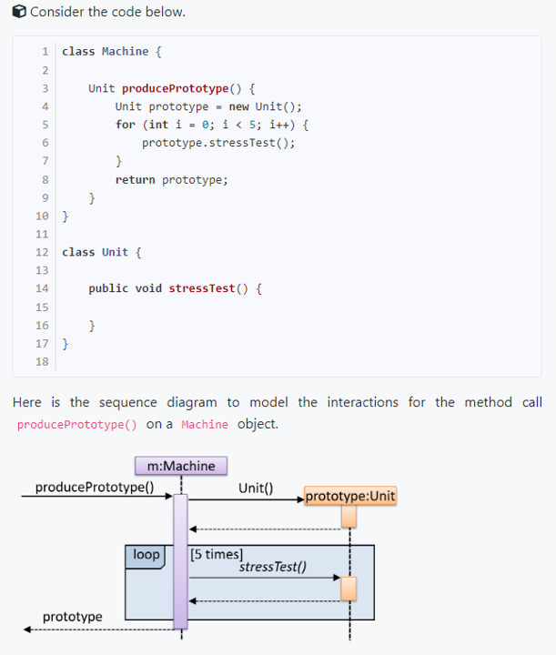
Basic Notation of Sequence Diagrams:
Terms to take note of: Entities, Activation bar, Operation invoked, return (of control / return value), Lifeline.
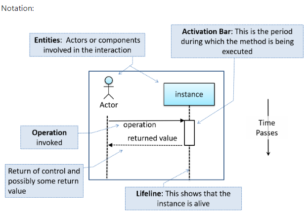
- Arrows representing method calls should be solid arrows while those representing method returns should be dashed arrows.
- Note that unlike in object diagrams, the class/object name is not underlined in sequence diagrams.
- The arrowhead style depends on the type of method call.
- Synchronous (blocked until returns) should use filled arrowheads.
- Asynchronous method calls are showed using lined arrow heads.
- Make sure ends of activation bar (period where method executed) is where arrows point, and make sure activation bar is not broken even if it calls another secondary method.
Sequence Diagram Loops, Object Creation:
For object creation, arrow that arrives at side of box representing instance is the constructor. Activation bar represents period constructor is active.
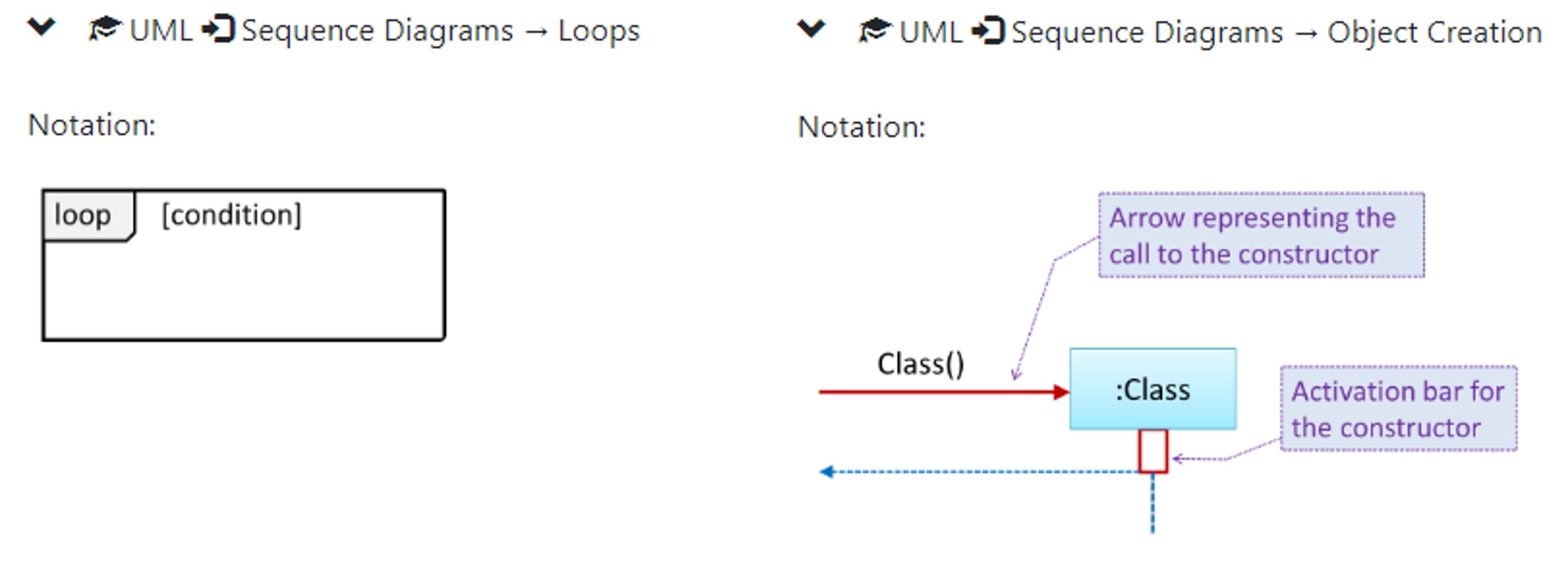
Minimal Notation: optional elements (e.g, activation bars, return arrows) may be omitted if the omission does not result in ambiguities or loss of relevant information.
Sequence Diagrams: Intermediate, Advanced
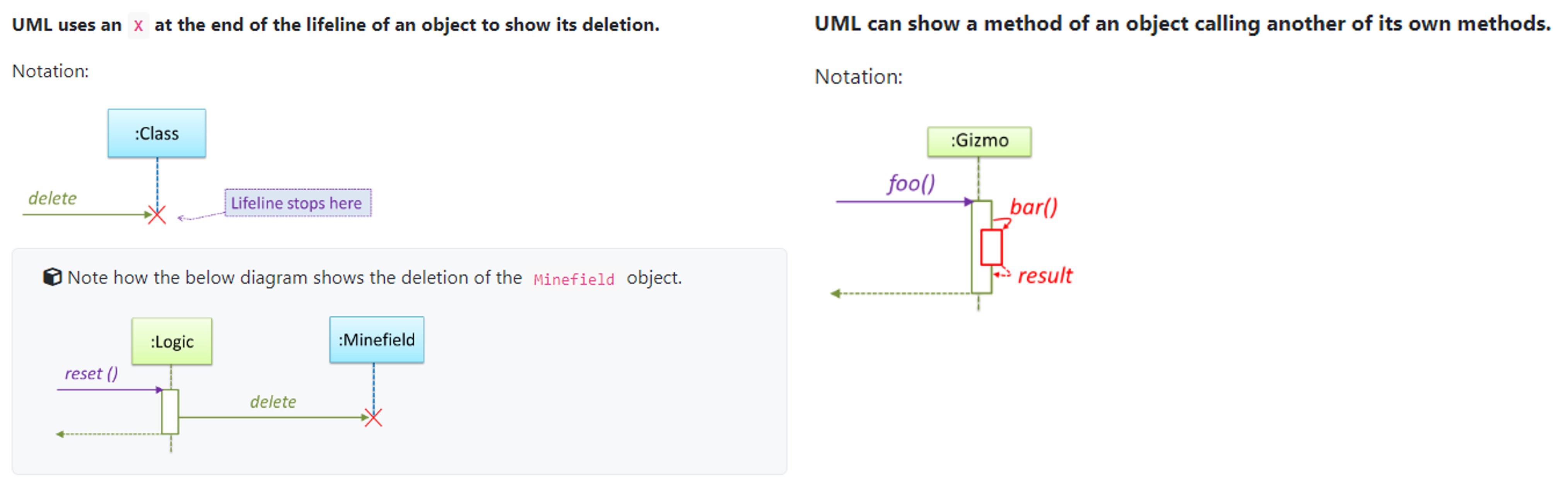
Object Deletion, Self Invocation
Objection Deletion: UML uses an X at the end of the lifeline of an object to show its deletion. Although languages such as Java do not support a delete operation (because they use automatic memory management), you can use the object deletion notation to indicate the point at which the object becomes ready to be garbage-collected (i.e., the point at which it ceases to be referenced).
UML can also show a method of an object calling another of its own methods.
Alternative Paths, Optional Paths, Calls to static methods
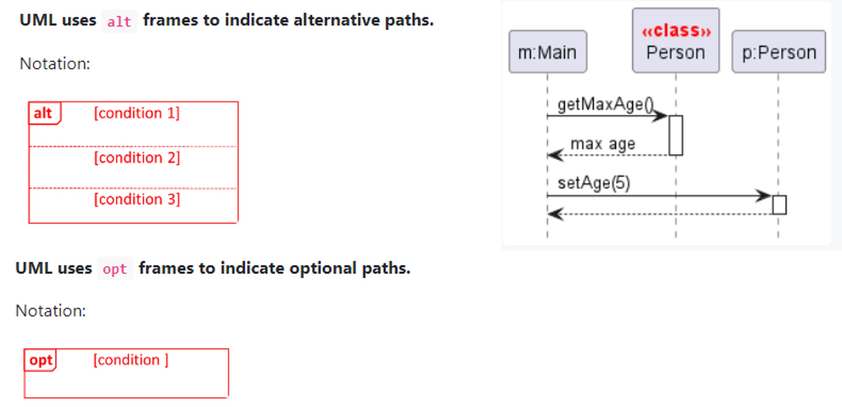
UML uses alt frames to indicate alternative paths.
- No more than one alternative partitions be executed in a
altframe. That is, it is acceptable for none of the alternative partitions to be executed, but it is not acceptable for multiple partitions to be executed.
UML uses opt frames to indicate optional paths.
Method calls to static (i.e., class-level) methods are received by the class itself, not an instance of that class. You can use <<class>> to show that a participant is the class itself.
Parallel Paths, Reference Frames (Reference another seq. Diagram)
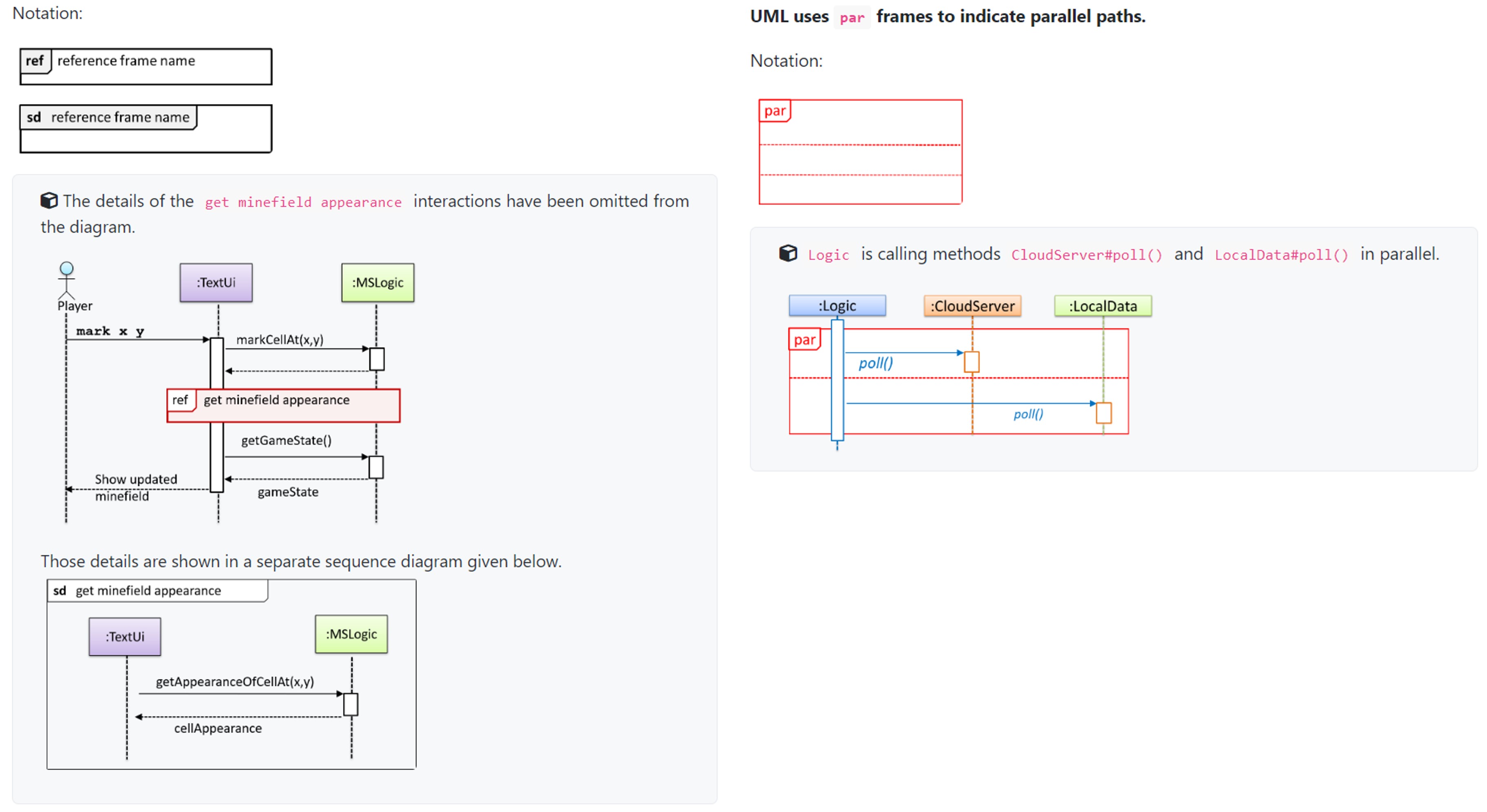
UML uses
parframes to indicate parallel paths.UML uses
refframe to allow a segment of the interaction to be omitted and shown as a separate sequence diagram. Reference frames help you to break complicated sequence diagrams into multiple parts or simply to omit details you are not interested in showing.
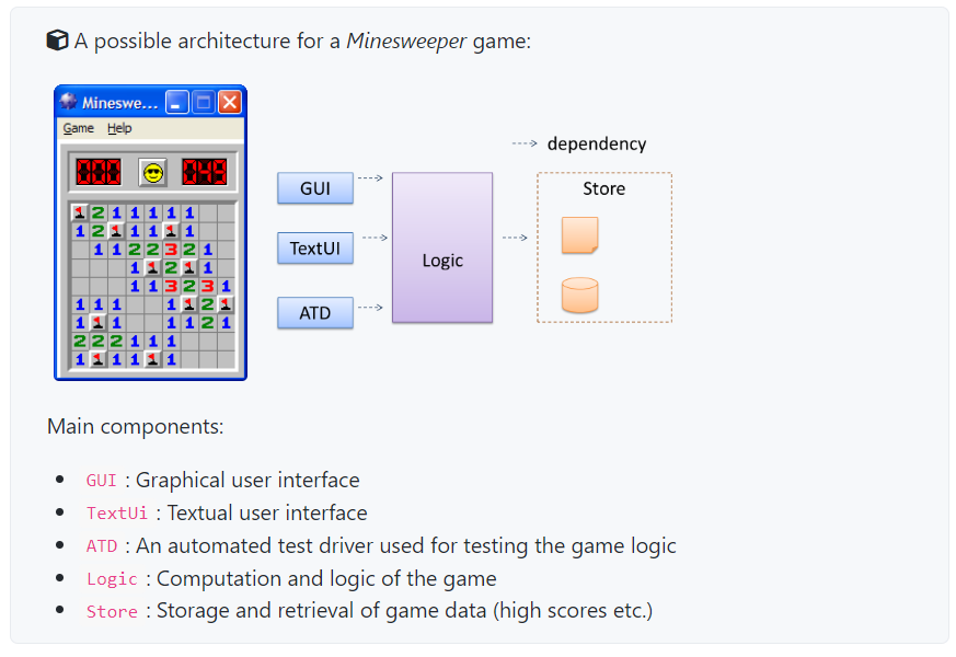
Architecture Diagrams (High Level Design)
The software architecture of a program or computing system is the structure(s) of the system, which comprise software elements, the externally visible properties of those elements, and the relationships among them.
Architecture is concerned with the public side of interfaces; private details of elements—details having to do solely with internal implementation—are not architectural.
The software architecture shows the overall organization of the system and can be viewed as a very high-level design.
- Usually consists of a set of interacting components that fit together to achieve required functionality.
- Should be simple & technically viable structure, well-understood, agreed-upon by everyone.
- Forms the basis for the implementation.
Typically designed by software architect. Provides technical vision and makes high level technical decisions.
Architecture diagrams are free-form diagrams. There is no universally adopted standard notation for architecture diagrams. Any symbols that reasonably describe the architecture may be used.
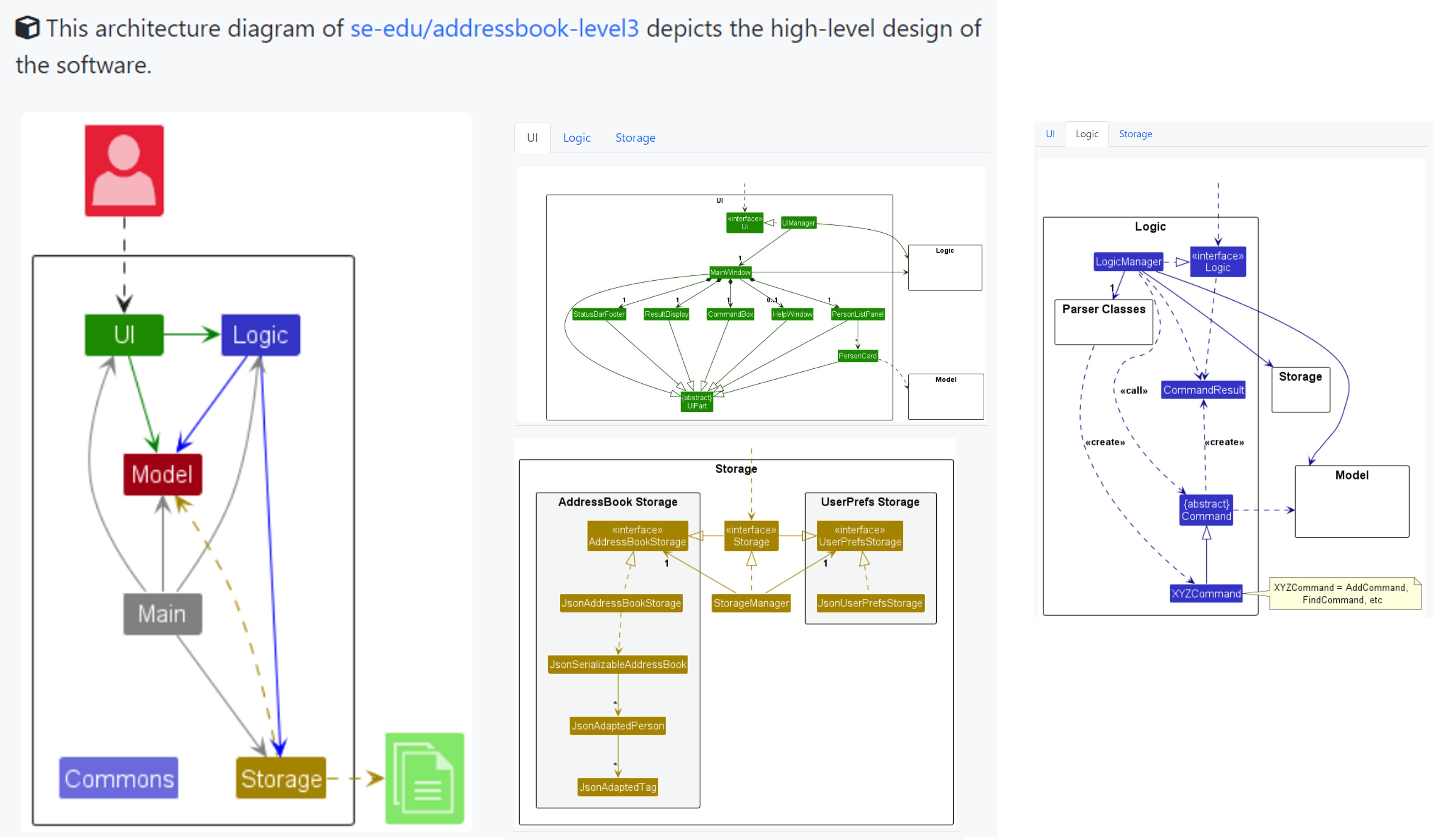
Multi-Level Design
- In a smaller system, the design of the entire system can be shown in one place.
- The design of bigger systems needs to be done/shown at multiple levels.
IDEs: Intermediate, Advanced Features
Debugging
Debugging is the process of discovering defects in the program. Here are some approaches to debugging:
- Inserting temporary print statements may be bad, as it Incurs extra effort inserting and removing, increase risk of introducing errors and if not removed promptly may even appear unexpectedly in the production version.
- Eyeballing: By manually tracing through the code, may be difficult, time consuming, error prone.
Instead, use a debugger!
- A debugger tool allows you to pause the execution, then step through the code one statement at a time while examining the internal state if necessary. Most IDEs come with an inbuilt debugger. This is the recommended approach for debugging.
Code Navigation:
- Quickly locate a file by name, goto definition of a method where used.
- Go back to previous location, View documentation of method where method is used, without navigating.
- Find where a method/field is being used.
Error Handling: Logging
Logging is the deliberate recording of certain information during a program execution for future reference. Logs are typically written to a log file but it is also possible to log information in other ways e.g. into a database or a remote server.
Logging can be useful for troubleshooting problems. A good logging system records some system information regularly. When bad things happen to a system e.g. an unanticipated failure, their associated log files may provide indications of what went wrong and actions can then be taken to prevent it from happening again.
- Most programming environments come with logging systems that allow sophisticated forms of logging. They have features such as the ability to enable and disable logging easily or to change the logging intensity.
Productivity Shortcuts
See IntelliJ IDEA productivity shortcuts video. Link
CS2103T Week 7 Topics
Use Cases
Use case: A description of a set of sequences of actions, including variants, that a system performs to yield an observable result of value to an actor [ 📖 : uml-user-guide].
Use case describes interaction between user and system for a specific functionality of system.
UML includes diagram type called use case diagrams the can illustrate use cases of a system visually.
Captures functional requirements of system.
Identifying Use Cases
Terms:
- Actor: Actor in use case is role played by user, can be human or another system. Not part of system, reside outside of system.
- E.g. Guest, Student, Staff, Admin, Libsys.
- Use case can involve multiple actors, actor can be involved in many use cases. A person/system can play many roles / single role.
- Use cases can be specified at various LoD. (levels of detail).
- When modeling interactions, start with high level use cases, progressively towards lower level use cases. Don’t mix different levels.
Use Case Details
Writing Use Case Steps:
- The main body of the use case is a sequence of steps that describes the interaction between the system and the actors. Each step is given as a simple statement describing who does what.
- A use case describes only the externally visible behavior, not internal details, of a system.
- A step gives the intention of the actor (not the mechanics). That means UI details are usually omitted.
- A use case description can show loops too.
Main Success Scenario MSS
Main Success Scenario (MSS):
- The Main Success Scenario (MSS) describes the most straightforward interaction for a given use case, which assumes that nothing goes wrong. This is also called the Basic Course of Action or the Main Flow of Events of a use case.
- Does not tell us if enters incorrect data / timeout, network outage.
Use Case Inclusion, Extension, Preconditions, Guarantees
Extensions:
- Extensions are “add-on”s to the MSS that describe exceptional/alternative flow of events. They describe variations of the scenario that can happen if certain things are not as expected by the MSS. Extensions appear below the MSS.
Example:
1
2
3
4
5
6
7
8
9
10
11
12
13
14
15
16
17
18
19
20
21
22
23
24
25
26
27
28
29
30
31
32
System: Online Banking System (OBS)
Use case: UC23 - Transfer Money
Actor: User
MSS:
  1. User chooses to transfer money.
  2. OBS requests for details of the transfer.
  3. User enters the requested details.
  4. OBS requests for confirmation.
  5. User confirms.
  6. OBS transfers the money and displays the new account balance.
  Use case ends.
Extensions:
  3a. OBS detects an error in the entered data.
      3a1. OBS requests for the correct data.
      3a2. User enters new data.
      Steps 3a1-3a2 are repeated until the data entered are correct.
      Use case resumes from step 4.

  3b. User requests to effect the transfer in a future date.
      3b1. OBS requests for confirmation.
      3b2. User confirms future transfer.
      Use case ends.

  *a. At any time, User chooses to cancel the transfer.
      *a1. OBS requests to confirm the cancellation.
      *a2. User confirms the cancellation.
      Use case ends.

  *b. At any time, 120 seconds lapse without any input from the User.
      *b1. OBS cancels the transfer.
      *b2. OBS informs the User of the cancellation.
      Use case ends.
- Numbering style is not universal, but widely used.
- MSS should be self-contained.
- Not really useful to mention power failures, crashes as extensions since system cannot function beyond such failures.
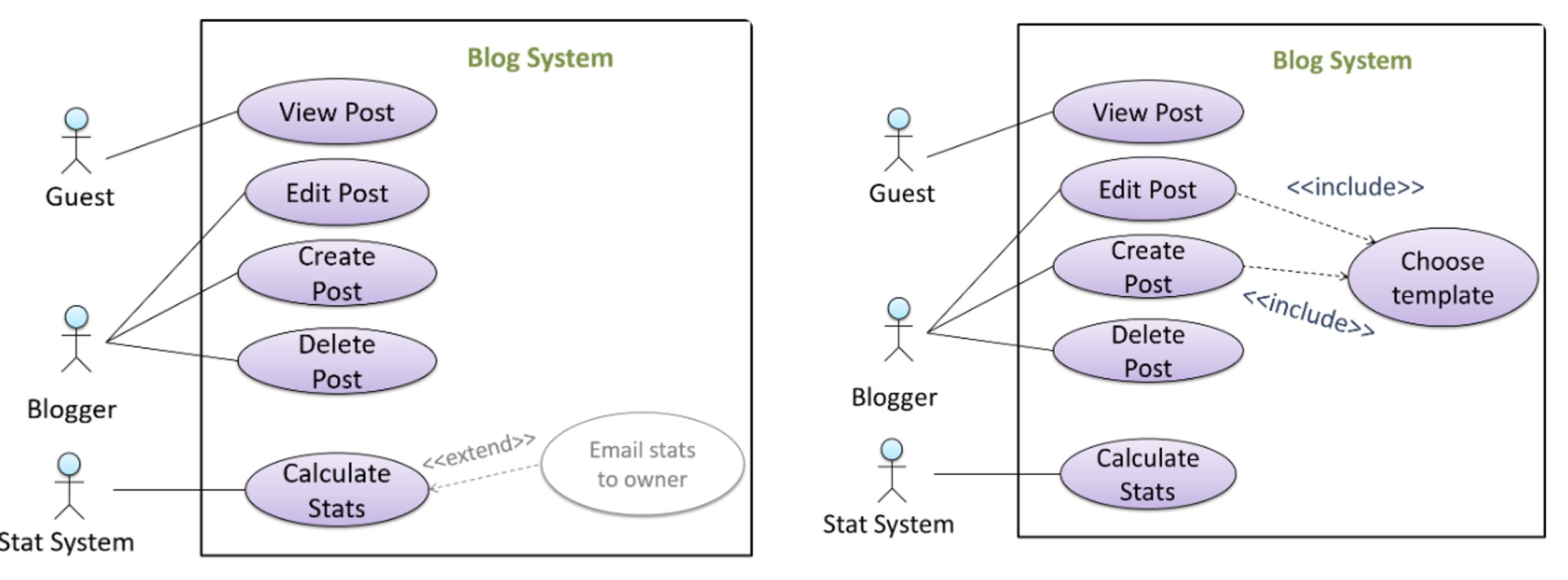
- In use case diagrams you can use the «extend» arrows to show extensions. Note the direction of the arrow is from the extension to the use case it extends and the arrow uses a dashed line.
Inclusions: A use case can include another use case. Underlined text is used to show an inclusion of a use case.
1
2
3
4
5
6
7
8
Software System: LearnSys
Use case: UC01 - Conduct Survey
Actors: Staff, Student
MSS:
Staff creates the survey (UC44).
Student completes the survey (UC50).
Staff views the survey results.
Use case ends.
- Useful to declutter low-level steps, or when set of steps repeated in multiple use cases.
- Use dotted arrow and
<<includes>>annotation to show use case inclusions. Not arrow direction is different from<<extends>>arrows.
Preconditions
- Preconditions specify the specific state you expect the system to be in before the use case starts.
- E.g.
Preconditions: User is logged in.
- E.g.
Guarantees
- Guarantees specify what the use case promises to give us at the end of its operation.
- E.g.
Money will be deducted from the source account only if the transfer to the destination account is successful. The transfer will not result in the account balance going below the minimum balance required.
- E.g.
Use Cases Usage Optimization:
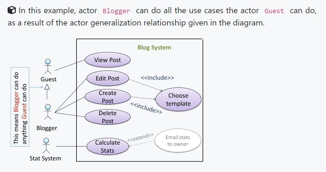
You can use actor generalization in use case diagrams using a symbol similar to that of UML notation for inheritance.
- Do not over-complicate use case diagrams by trying to include everything possible.
Some include ‘System’ as an actor to indicate that something is done by the system itself without being initiated by a user or an external system.
- Recommended not to show system as user, and limit use cases for modeling behaviors that involve external actors.
UML not specific about text contents of use cases, with many styles.
Advantages of documenting system requirements as use cases:
- Simple and plain, easy for user to understand, give feedback.
- Decouple user intention from mechanism.
- Identifying all extensions encourages considerations of situations software pdt may face during operation.
- Separating typical from special cases encourages optimizing typical scenario.
One of the main disadvantages of use cases is that they are not good for capturing requirements that do not involve a user interacting with the system. Hence, they should not be used as the sole means to specify requirements
Design: High Level Concepts
Design: Creative process of transforming a problem into a solution, where the solution is also called design.
Software Design:
- Two main aspects
- Product / External Design: Designing external behavior of product to meet user requirements. (Usually done by product designers, e,g, UX, UI, business analyst)
- Implementation / Internal Design: Designing product implementation to meet required external behavior. (Usually done by software achitects, SWE).
Course focuses more on internal design.
Design Approaches: Top-down and Bottom-up.
Multi-level design can be done in a top-down manner, bottom-up manner, or as a mix.
- Top-down: Design the high-level design first and flesh out the lower levels later.
- Especially useful when designing big and novel systems where the high-level design needs to be stable before lower levels can be designed.
- Bottom-up: Design lower level components first and put them together to create the higher-level systems later.
- Not usually scalable for bigger systems. One instance where this approach might work is when designing a variation of an existing system or re-purposing existing components to build a new system.
- Mix: Design the top levels using the top-down approach but switch to a bottom-up approach when designing the bottom levels.
Agile Design
Agile design can be contrasted with full upfront design in the following way:
- Agile designs are emergent, they’re not defined up front. Your overall system design will emerge over time, evolving to fulfill new requirements and take advantage of new technologies as appropriate.
- Although some initial architectural modeling at beginning of a project, this will be just enough to get your team going. This approach does not produce a fully documented set of models in place before you may begin coding. – adapted from agilemodeling.com
Design: Fundamentals: Abstraction, Coupling, Cohesion.
3 Fundamental Design Concepts: Abstraction, Coupling, Cohesion.
- Increase Abstraction, Reduce Coupling and Increase Cohesion.
Abstraction:
The guiding principle of abstraction is that only details that are relevant to the current perspective or the task at hand need to be considered.
- As most programs are written to solve complex problems involving large amounts of intricate details, it is impossible to deal with all these details at the same time.
Data Abstraction:
- Abstracting away the lower level data items and thinking in terms of bigger entities
Control abstraction:
- Abstracting away details of the actual control flow to focus on tasks at a higher level
Abstraction can be applied repeatedly to obtain progressively higher levels of abstraction. Abstraction is a general concept that is not limited to just data or control abstractions. (OOP class, architecture, Models)
Coupling:
Coupling is a measure of the degree of dependence between components, classes, methods, etc. Low coupling indicates that a component is less dependent on other components. High coupling (aka tight coupling or strong coupling) is discouraged due to the following disadvantages:
- Harder maintenance as change in one module causes ripple effect.
- Integration is harder as multiple components need to be integrated at same time.
- Testing and resue is harder due to dependence.
Coupling Definition: X is coupled to Y if a change to Y can potentially require a change in X.
Some examples of coupling: A is coupled to B if,
- A has access to the internal structure of B (this results in a very high level of coupling)
- A and B depend on the same global variable
- A calls B
- A receives an object of B as a parameter or a return value
- A inherits from B
- A and B are required to follow the same data format or communication protocol
Types of Coupling:
- Content coupling: one module modifies or relies on the internal workings of another module e.g., accessing local data of another module
- Common/Global coupling: two modules share the same global data
- Control coupling: one module controlling the flow of another, by passing it information on what to do e.g., passing a flag
- Data coupling: one module sharing data with another module e.g. via passing parameters
- External coupling: two modules share an externally imposed convention e.g., data formats, communication protocols, device interfaces.
- Subclass coupling: a class inherits from another class. Note that a child class is coupled to the parent class but not the other way around.
- Temporal coupling: two actions are bundled together just because they happen to occur at the same time e.g. extracting a contiguous block of code as a method although the code block contains statements unrelated to each other
Cohesion
Cohesion is a measure of how strongly-related and focused the various responsibilities of a component are. A highly-cohesive component keeps related functionalities together while keeping out all other unrelated things.
Higher cohesion is better.
Disadvantages of low cohesion:
- Lowers the understandability of modules as difficult to express module functionalities at a higher level.
- Lowers maintainability as module can be modified due to unrelated causes (reason: the module contains code unrelated to each other) or many modules may need to be modified to achieve a small change in behavior (reason: because the code related to that change is not localized to a single module).
- Lowers reusability of modules because they do not represent logical units of functionality.
Forms of Cohesion:
- Cohesion can present in many forms. E.g.
- Code related to single concept kept together
- Code invoked close together in time kept together (e.g. initializing system code)
- Code that manipulates same data structure kept together.
Integration Approaches
Late & One time vs. Early & Frequent
In terms of timing and frequency, there are two general approaches to integration: late and one-time, early and frequent.
Late and one-time: wait till all components are completed and integrate all finished components near the end of the project.
- Approach not recommended as integration often causes many component incompatibilities, leading to delivery delays.
Early and frequent: integrate early and evolve each part in parallel, in small steps, re-integrating frequently.
A walking skeleton can be written first. This can be done by one developer, possibly the one in charge of integration. After that, all developers can flesh out the skeleton in parallel, adding one feature at a time. After each feature is done, simply integrate the new code into the main system.
Big-bang vs. Incremental Integration
Big-bang integration: integrate all components at the same time.
Incremental integration: integrate a few components at a time. This approach is better than big-bang integration because it surfaces integration problems in a more manageable way.
Top-down vs. Bottom-up Integration
Incremental integration can be done differently based on order in which components are integrated.
- Top-down integration: higher-level components are integrated before bringing in the lower-level components.
- One advantage of this approach is that higher-level problems can be discovered early.
- One disadvantage is that this requires the use of stubs in place of lower level components until the real lower-level components are integrated into the system.
- Otherwise, higher-level components cannot function as they depend on lower level ones.
Bottom-up integration: the reverse of top-down integration. Note that when integrating lower level components, drivers may be needed to test the integrated components because the UI may not be integrated yet, just like how top-down integration needs stubs.
- Sandwich integration: a mix of the top-down and bottom-up approaches. The idea is to do both top-down and bottom-up so as to ‘meet’ in the middle.
Project Mgmt: Scheduling & Tracking
Milestones
A milestone is the end of a stage which indicates significant progress.
- You should take into account dependencies and priorities when deciding on the features to be delivered at a certain milestone.
Each intermediate product release is a milestone.
Buffers, Issue Trackers
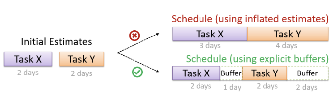
A buffer is time set aside to absorb any unforeseen delays. It is very important to include buffers in a software project schedule because effort/time estimations for software development are notoriously hard.
- Do not inflate task estimates to create hidden buffers; have explicit buffers instead.
- Reason: With explicit buffers, it is easier to detect incorrect effort estimates which can serve as feedback to improve future effort estimates.
Issue Trackers: Keeping track of project tasks (who is doing what, which tasks are ongoing, which tasks are done etc.) is an essential part of project management. In small projects, it may be possible to keep track of tasks using simple tools such as online spreadsheets or general-purpose/light-weight task tracking tools such as Trello. Bigger projects need more sophisticated task tracking tools.
Issue trackers (sometimes called bug trackers) are commonly used to track task assignment and progress. Most online project management software such as GitHub, SourceForge, and BitBucket come with an integrated issue tracker.
Work Breakdown Structure (WBS)
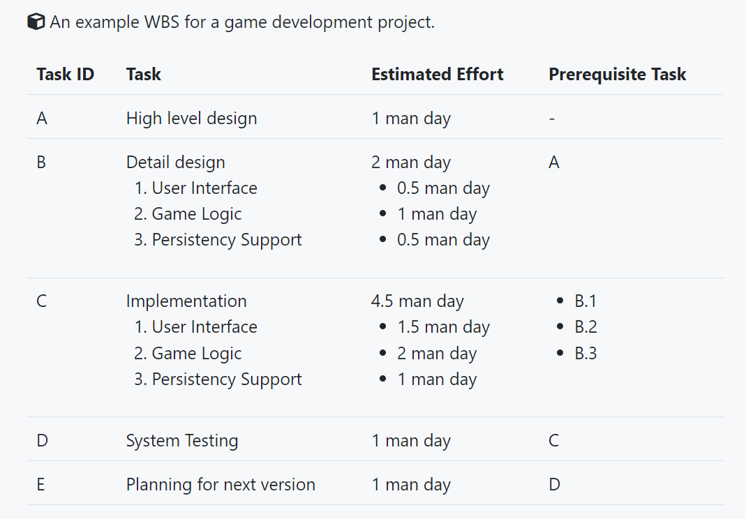
Work Breakdown Structure depicts information about tasks and their details in terms of subtasks.
When managing projects, it is useful to divide the total work into smaller, well-defined units. Relatively complex tasks can be further split into subtasks. In complex projects, a WBS can also include prerequisite tasks and effort estimates for each task.
The effort is traditionally measured in man hour/day/month i.e. work that can be done by one person in one hour/day/month. The Task ID is a label for easy reference to a task.
- Simple labeling is suitable for a small project, while a more informative labeling system can be adopted for bigger projects.
All tasks should be well-defined. This means it should be clear as to when the task will be considered done.
Gantt Chart: A Gantt chart is a 2-D bar-chart, drawn as time vs tasks (represented by horizontal bars).
PERT Chart: A PERT (Program Evaluation Review Technique) chart uses a graphical technique to show the order/sequence of tasks. It is based on the simple idea of drawing a directed graph in which:
- Nodes or vertices capture the effort estimations of tasks.
- Arrows depict the precedence between tasks
Critical path is the path in which any delay can directly affect the project duration. It is important to ensure tasks on the critical path are completed on time.
Team Structures
Given below are three commonly used team structures in software development. Irrespective of the team structure, it is a good practice to assign roles and responsibilities to different team members so that someone is clearly in charge of each aspect of the project.
- In comparison, the ‘everybody is responsible for everything’ approach can result in more chaos and hence slower progress.
- Egoless Team (All equal in responsibility, accountability. However, higher risk of falling apart, absence of authority figure.)
- Chief Programmer Team (Similar to medical surgical team, there is a single authoritative figure. Chief programmer must be superb technical hand and have good managerial skills)
- Strict hierarchy Team. (Strictly defined organization among team members).
Project Mgmt: Workflows
Forking Flow
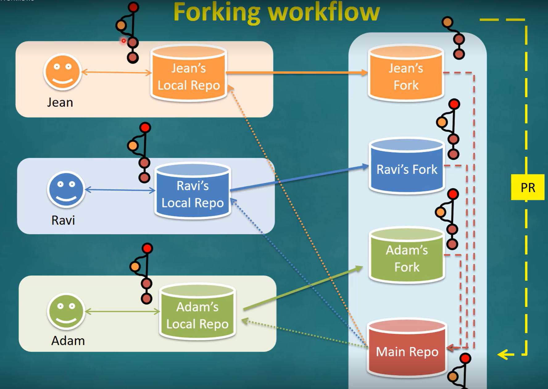
In the forking workflow, the ‘official’ version of the software is kept in a remote repo designated as the ‘main repo’. All team members fork the main repo and create pull requests from their fork to the main repo.
Revision Control: DRCS vs CRCS
RCS can be done centralized or distributed.
Centralized RCS (CRCS for short) uses a central remote repo that is shared by the team. Team members download (‘pull’) and upload (‘push’) changes between their own local repositories and the central repository.
Distributed RCS (DRCS for short, also known as Decentralized RCS) allows multiple remote repos and pulling and pushing can be done among them in arbitrary ways. The workflow can vary differently from team to team.
Feature Branch Flow, Centralized Flow
Feature branch workflow is similar to forking workflow except there are no forks. Everyone is pushing/pulling from the same remote repo. The phrase feature branch is used because each new feature (or bug fix, or any other modification) is done in a separate branch and merged to the master branch when ready. Pull requests can still be created within the central repository, from the feature branch to the main branch.
The centralized workflow is similar to the feature branch workflow except all changes are done in the master branch.